Categories
- Support & Resources (31)
- Pipes & Fittings (35)
- Valves & Pumps (71)
- Instruments & Tools (23)
- Equipment, Chemicals & Consumables (25)
Efficient air management is the backbone of a safe and high-performing water distribution system. The Metalsin‘s Standard Dual-Chamber Combination Air Valve is a heavy-duty, triple-function solution designed to protect large-diameter pipelines from entrapped air and catastrophic vacuum collapse. By physically isolating the large-volume air management from the high-pressure micro-venting, this dual-chamber design offers unparalleled reliability in the most demanding environments.
The Metalsin standard dual-chamber series consist of two parallel chambers connected to the main pipeline via a common bottom flange:
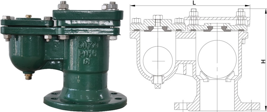
A typical standard dual-chamber combination air valve, furnished with the technical drawing.
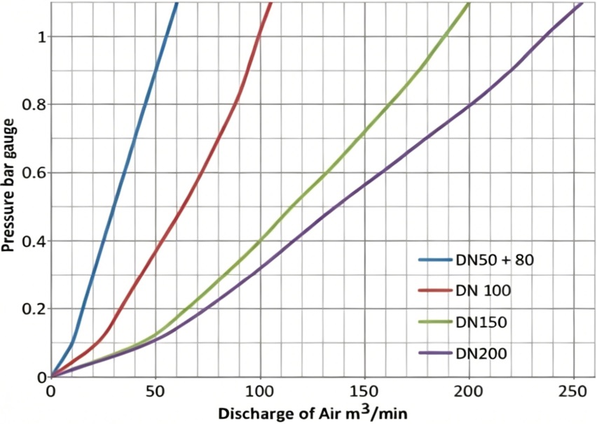
Air discharging flow chart for the large orifice of a STD dual-chamber combination air valve.
Large-volume exhaust phase (initial filling): During the initial filling of an empty pipeline, massive volumes of air are pushed forward by the incoming water flow. Since the chambers are devoid of water at this stage, the large float on the right remains at its lowest position, leaving the large kinetic orifice fully open. This allows air to be exhausted at high velocity, ensuring a smooth filling process. While the small orifice on the left also vents air simultaneously, its discharge volume is negligible compared to the massive airflow passing through the primary kinetic port.
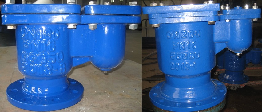
Ductile iron standard dual-chamber combination air valves: PN-16 flanged end, FBE coating, 4″ & 8″.
Micro-venting under pressure phase (operational stage): Once filling is complete and water fills both chambers, both floats rise with the water level to seal the orifices, allowing the system to enter its high-pressure operational state. During normal operation, entrained air released from the water gradually accumulates at the top of the small automatic chamber. When the accumulated air displaces enough water to lower the liquid level, the small float descends to precisely open the micro-venting orifice. During this phase, the large kinetic orifice remains tightly sealed due to high internal pressure and a lack of mechanical leverage, allowing the small chamber to continuously “breathe” out accumulated micro-bubbles without disturbing the main system pressure.
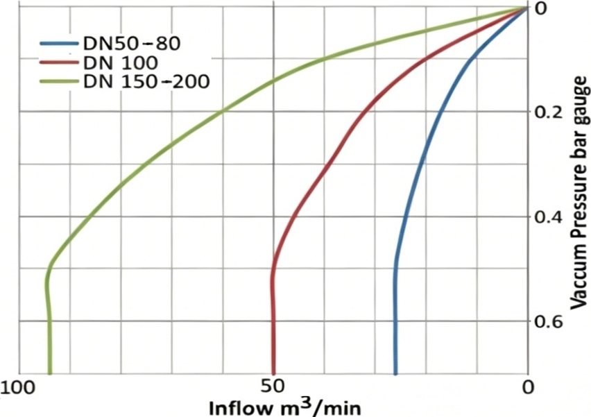
The air intake flow chart for large orifice of the STD dual-chamber air valve.
Vacuum relief phase (system protection): The air valve provides critical protection in the event of a power failure or a pipe burst, where internal pressure drops sharply into a negative (vacuum) state. As water rapidly retreats from the chambers, the large float on the right instantaneously loses buoyancy and drops, fully opening the large orifice. This admits a massive volume of atmospheric air into the pipeline to break the vacuum. This function acts as a “safety airbag” for the infrastructure, preventing the pipeline from collapsing or suffering structural damage due to excessive external-to-internal pressure differentials.
Standard dual-chamber combination air valve:
| DN | L mm | H mm |
|---|---|---|
| 25 | 147 | 185 |
| 40 | 224 | 187 |
| 50 | 273 | 214 |
| 65 | 273 | 214 |
| 80 | 283 | 244 |
| 100 | 302 | 270 |
| 125 | 353 | 323 |
| 150 | 353 | 323 |
| 200 | 433 | 401 |
| 250 | 491 | 450 |
| Full Series of Air Valves | |
|---|---|
| Air Release/Venting Valve | Air/Vacuum Valve |
| Single-Body Combination | Plastic Combination Series |
| Dual-Chamber Combination | Combination w/t Isolation Gate |